Problème Afficheur 16x2 PIC16F84A ASM
Répondre à la discussion
Affichage des résultats 1 à 10 sur 10

Problème Afficheur 16x2 PIC16F84A ASM


  1. #1
    Delta-B

    Problème Afficheur 16x2 PIC16F84A ASM


    ------

    Bonjour a tous,

    J'ai déjà regardé l'ensemble des posts relatifs aux problèmes d'afficheur et je n'ai pas trouvé de solution malgré mes nombreux tests. Je m'en réfère donc a votre expérience.
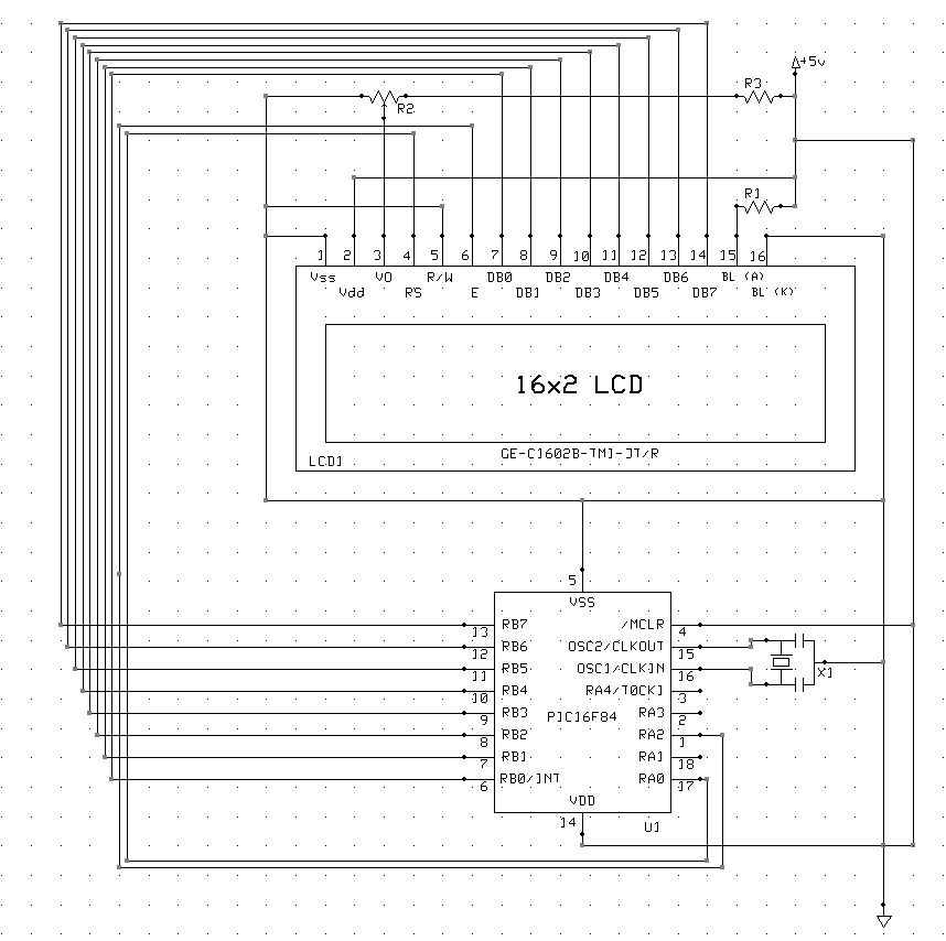
    µC : PIC 16F84A
    Afficheur LCD : Gleichmann GE-C1602B-TMI-JT/R

    Voici le Schema de montage :

    Nom : schemaLCD.JPG
Affichages : 369
Taille : 109,4 Ko

    alimenté VDC +5V
    PORTB sert donc a l'envoi des données
    PORTA,1 => RS
    PORTA,2 => E

    Le soucis est le suivant : Mon afficheur s'allume et tout les pixels de mon LCD sont allumés (Gros carrés blancs sur fond bleu), le contraste ne change rien.
    La premiere ligne clognotte à une fréquence de 1Hz et la ligne du dessous (aussi remplie de cases blanches) reste fixe. D'ailleurs le contraste ne l'affecte pas.

    j'ai initialisé TRISA et TRISB a 0x00 (toutes des sorties)

    Voici le code sensé écrire "Hello" sur mon afficheur, j'ai laissé un bonne tempo (100ms) entre chaque instructions et je n'ai pas oublié le pin E H=>L.

    Code:
    	LIST      p=16F84            ; Définition de processeur
    	#DEFINE	__16F84	16F84
    	#include <p16F84.inc>        ; Définitions des constantes
    	radix dec					 ; on travaille en décimal par défaut
    
    	errorlevel -302
    
    	__CONFIG   _CP_OFF & _WDT_OFF & _PWRTE_ON & _HS_OSC
    
    ; '__CONFIG' précise les paramètres encodés dans le processeur au moment de
    ; la programmation. Les définitions sont dans le fichier include.
    ; Voici les valeurs et leurs définitions :
    ;	_CP_ON				Code protection ON : impossible de relire
    ;	_CP_OFF				Code protection OFF
    ;	_PWRTE_ON			Timer reset sur power on en service
    ;	_PWRTE_OFF			Timer reset hors-service
    ;	_WDT_ON				Watch-dog en service
    ;	_WDT_OFF			Watch-dog hors service
    ;	_LP_OSC				Oscillateur quartz basse vitesse
    ;	_XT_OSC				Oscillateur quartz moyenne vitesse
    ;	_HS_OSC				Oscillateur quartz grande vitesse
    ;	_RC_OSC				Oscillateur à réseau RC
    
    ;*********************************************************************
    ;                              ASSIGNATIONS                          *
    ;*********************************************************************
    
    OPTIONVAL	EQU	H'40'			; Valeur registre option
                                    ; Résistance pull-up ON
                                    ; Interrupt flanc montant RB0
                                    ; Préscaler timer à 2 (exemple)
    
    INTERMASK	EQU	H'90' 		; Masque d'interruption
                                    ; Interruptions sur RB0 (exemple)
    
    
    ;*********************************************************************
    ;                             DEFINE                                 *
    ;*********************************************************************
    
    ; exemple
    ; -------
    #DEFINE LCD_E	PORTA,2
    #DEFINE	LCD_RS	PORTA,1
    
    ;*********************************************************************
    ;                             MACRO                                  *
    ;*********************************************************************
    
    BANK0	macro
    		bcf	STATUS,RP0			; passer banque0
    		endm
    
    BANK1	macro
    		bsf	STATUS,RP0			; passer banque1
    		endm
    
    ;*********************************************************************
    ;                   DECLARATIONS DE VARIABLES                        *
    ;*********************************************************************
    
    ;exemples
    ;---------
    	CBLOCK 0x00C   				; début de la zone variables
    	w_temp :1					; Sauvegarde du registre W
    	status_temp : 1				; Sauvegarde du registre STATUS
    	w1 : 1
    	w2 : 1
    	ENDC						; Fin de la zone                        
    
    ;**********************************************************************
    ;                      DEMARRAGE SUR RESET                            *
    ;**********************************************************************
    
    	org 	0x000		 		; Adresse de départ après reset
      	goto    init				; Adresse 0: initialiser
    
    
    ;*********************************************************************
    ;                       INITIALISATIONS                              *
    ;*********************************************************************
    
    init
    	clrf	PORTA				; Sorties portA à 0
    	clrf	PORTB				; sorties portB à 0
    	BANK1						; passer banque1
    	movlw	OPTIONVAL			; charger masque
    	movwf	OPTION_REG			; initialiser registre option
    
    			; Effacer RAM
    			; ------------
    	movlw	0x0c				; initialisation pointeur
    	movwf	FSR					; pointeur d'adressage indirect
    init1
    	clrf	INDF				; effacer ram
    	incf	FSR,f				; pointer sur suivant
    	btfss	FSR,6				; tester si fin zone atteinte (>=40)
    	goto	init1				; non, boucler
    	btfss	FSR,4				; tester si fin zone atteinte (>=50)
    	goto	init1				; non, boucler


    	clrf	TRISA
    	clrf	TRISB
    	BANK0						; passer banque0
    
    	movlw	INTERMASK			; masque interruption
    	movwf	INTCON				; charger interrupt control
    	goto	start				; sauter programme principal
    
    
    ;*********************************************************************
    ;                      PROGRAMME PRINCIPAL                           *
    ;*********************************************************************
    
    	errorlevel +302
    
    wait100ms
    	movlw	97
    	movwf	w2
    w2L
    	clrf	w1
    w1L
    	decfsz	w1,f
    		goto w1L
    	decfsz	w2,f
    		goto w2L
    	return
    
    start
    	call	wait100ms
    	
    	bsf		LCD_E
    	movlw	b'00110000'			; 8bit-command
    	movwf	PORTB
    	nop
    	nop
    	bcf		LCD_E				; Send
    	call	wait100ms
    
    	bsf		LCD_E
    	nop
    	nop
    	BCF		LCD_E				; Resend
    	call	wait100ms
    	
    	bsf		LCD_E
    	nop
    	nop
    	bcf		LCD_E				; Resend
    	call	wait100ms
    	
    	bsf		LCD_E
    	movlw	b'00111000'			; 8bit + 2 Lines small fonts
    	movwf	PORTB
    	nop
    	nop
    	bcf		LCD_E				; Send
    	call 	wait100ms
    	
    	bsf		LCD_E
    	movlw	b'00001000'			;Display OFF
    	movwf	PORTB
    	nop
    	nop
    	bcf		LCD_E				; Send
    	call 	wait100ms
    	
    	bsf		LCD_E
    	movlw	b'00000001'			; Clear Display
    	movwf	PORTB
    	nop
    	nop
    	bcf		LCD_E				;Send
    	call 	wait100ms
    	
    	bsf		LCD_E
    	movlw	b'00000110'			; Move Left Cursor no shift
    	movwf	PORTB
    	nop
    	nop
    	bcf		LCD_E				;Send
    	call	wait100ms
    	
    	bsf		LCD_RS				; Activation des caractères
    	
    	bsf		LCD_E
    	movlw	b'01001000'
    	movwf	PORTB
    	nop
    	nop
    	bcf		LCD_E
    	call	wait100ms
    	
    	movlw	b'01100101'
    	movwf	PORTB
    	bsf		LCD_E
    	nop
    	bcf		LCD_E
    	call	wait100ms
    
    	movlw	b'01101100'
    	movwf	PORTB
    	bsf		LCD_E
    	bcf		LCD_E
    	call	wait100ms
    
    	movlw	b'01101100'
    	movwf	PORTB
    	bsf		LCD_E
    	bcf		LCD_E
    	call	wait100ms
    	
    	movlw	b'01101111'			; o
    	movwf	PORTB
    	bsf		LCD_E
    	bcf		LCD_E
    	call	wait100ms
    
    	bsf		LCD_E
    	movlw	b'00001100'			;Display ON
    	movwf	PORTB
    	nop
    	nop
    	bcf		LCD_E				; Send
    	call 	wait100ms
    
    start2
    	nop
    	nop
    	nop
    	nop
    	goto start2					; boucler
    
    	END 						; directive fin de programme
    J'ai aussi tenté d'initialiser e display à ON d'emblée de programme mais, le problème est identique...

    Merci pour votre aide !

    -----

  2. #2
    Delta-B

    Re : Problème Afficheur 16x2 PIC16F84A ASM

    Je souhaites juste rajouter qu'il y a une erreur sur le Schema, la pin RS du LCD est bien branchée sur RA1 et non RA0 comme sur la photo.

    100 merci

  3. #3
    elektrax

    Re : Problème Afficheur 16x2 PIC16F84A ASM

    valeur r3 et r2 ????

  4. #4
    Delta-B

    Re : Problème Afficheur 16x2 PIC16F84A ASM

    Comme sur le DataSheet du constructeur :

    R2 = Potentiometre de 2.2K ohm
    R3 = résistance de 10K ohm

    Pour info le pic fonctionne et ses ports aussi car le meme pic fonctionne impecablement sur d'autres circuits.

    Merci

  5. A voir en vidéo sur Futura
  6. #5
    paulfjujo

    Re : Problème Afficheur 16x2 PIC16F84A ASM

    bonjour,


    Ne pas oublier de laisser la place au vecteur d(interruption.. meme si on ne s'en sert pas, c'est une bonne habitude
    remplace la commande 06 ici, par la commande 02 = auto-inc (shift-cursor)
    Dans ton programme,revoir le placement de la pulse sur E

    Code:
    ; Origine lancement de programme
    	ORG     0x0000            
    RESET        GOTO    Init
    
    ; Interrupt routine.
         org     0x004
          nop
          nop
          nop
    
    Init 
     ......
      ...... etc ....
     ......
            bsf		LCD_E
    	movlw	b'00000001'			; Clear Display
    	movwf	PORTB
    	nop
    	nop
    	bcf		LCD_E				;Send
    	call 	wait100ms
    
    ; la commande 06 ici,est remplacee par la commande 02 = auto-inc (shift-cursor)
             bsf	       LCD_E
    	movlw	 0x02		; auto-inc (shift-cursor)
    	movwf	PORTB
    	nop
    	bcf	LCD_E				;Send
    	call	wait100ms
    	
    	bsf	LCD_RS				; Activation des caractères
    	
    	bsf	LCD_E
    	movlw	0x48	;=H= b'01001000'
    	movwf	PORTB
    	nop
    	bcf	LCD_E
    	call	wait100ms
    	
    	bsf	LCD_E
      	movlw	0x65	; =e= b'01100101'
    	movwf	PORTB
    	nop
    	bcf	LCD_E
    	call	wait100ms
    
    	bsf	LCD_E
    	movlw	0x6C	    ; = l=b'01101100'	
    	movwf	PORTB
    	nop
    	bcf	LCD_E
    	call	wait100ms
    
    	bsf	LCD_E
    	movlw	0x6C		;l
    	movwf	PORTB
    	nop
    	bcf	LCD_E
    	call	wait100ms
    	
    	bsf	LCD_E
    	movlw	 0x6F		;=o= b'01101111'
    	movwf	PORTB
    	nop
    	bcf	LCD_E
    	call	wait100ms
    
    start2
    	nop
    	nop
    	nop
    	nop
    	goto start2
    sinon compare ou essaie ce programme issu d'une note microchip AN587

    Code:
    	LIST P=16F84, F=INHX8M
    ;	ERRORLEVEL  2
    	__CONFIG _CP_OFF & _WDT_OFF & _XT_OSC
    
    ;*****************************************************************************
    ;
    ; This program interfaces to a Hitachi HD77480-based LC-Display
    ; Currently a 4 line * 20 characters display module.
    ;
    ; This program assembles for an 8-bit data interface.
    ; See AN587 for 4-bit and 8-bit interfaces.
    ;
    ; Program	LCD.ASM
    ; Last update	96-01-12
    ; Author	Peter Ouwehand
    ;
    ;*****************************************************************************
    ; Fosc		= 4MHz
    ; Cycle_time	= 1/Fosc / 4
    ;		= 1/(4*10^6) / 4
    ;		= 1uSec
    ;*****************************************************************************
    	include <p16f84.inc>
    
    ;*****************************************************************************
    ; Equates, I/O, vars
    ;*****************************************************************************
    RESET_V		EQU	0x0000		; Address of RESET Vector
    ISR_V		EQU	0x0004		; Address of Interrupt Vector
    OSC_FREQ	EQU	D'4000000'	; Oscillator Frequency is 4 MHz
    
    LCD_DATA	EQU	PORTB		; LCD data lines interface
    LCD_DATA_TRIS	EQU	TRISB
    LCD_CTRL	EQU	PORTA		; LCD control lines interface
    
    LCD_LINE0	EQU	0x000
    LCD_LINE1	EQU	0x040
    LCD_LINE2	EQU	0x014
    LCD_LINE3	EQU	0x054
    
    ; PORTA bits
    LCD_E		EQU	2		; LCD Enable control line
    LCD_RW		EQU	1		; LCD Read/Write control line
    LCD_RS		EQU	0		; LCD Register-Select control line
    
    ; PORTB bits
    DB7		EQU	7		; LCD dataline 7 (MSB)
    DB6		EQU	6		; LCD dataline 6
    DB5		EQU	5		; LCD dataline 5
    DB4		EQU	4		; LCD dataline 4
    DB3		EQU	3		; LCD dataline 3
    DB2		EQU	2		; LCD dataline 2
    DB1		EQU	1		; LCD dataline 1
    DB0		EQU	0		; LCD dataline 0 (LSB)
    
    ; misc.
    LCD_TEMP	EQU	0x020		; LCD subroutines internal use
    
    TABLE_INDEX	EQU	0x021		; Index to table strings
    COUNT		EQU	0x022		; A counter
    DELAY		equ	0x023		; Used in DELAYxxx routines
    X_DELAY		equ	0x024		; Used in X_DELAYxxx routines
    
    
    ;*****************************************************************************
    ; Program start
    ;*****************************************************************************
    	ORG	RESET_V			; RESET vector location
    RESET		GOTO	START
    
    
    ;*****************************************************************************
    ; This is the Periperal Interrupt routine. Should NOT get here
    ;*****************************************************************************
    	ORG	ISR_V			; Interrupt vector location
    INTERRUPT	BCF     STATUS, RP0	; Select bank 0
    		GOTO    INTERRUPT
    
    
    ;*****************************************************************************
    ; Initialize processor registers
    ;*****************************************************************************
    START					; POWER_ON Reset (Beginning of program)
    		CLRF	STATUS		; Do initialization, Select bank 0
    		CLRF	INTCON		; Clear int-flags, Disable interrupts
    		CLRF	PCLATH		; Keep in lower 2KByte
    
    		CLRF	PORTA		; ALL PORT output should output Low.
    		CLRF	PORTB
    
    		BSF	STATUS, RP0	; Select bank 1
    		MOVLW	0x0F8		; RA2-0 outputs, RA4-3 inputs
    		MOVWF	TRISA
    		MOVLW	0x000		; RB7-0 outputs
    		MOVWF	TRISB
    		BSF	OPTION_REG, NOT_RBPU
    					; Disable PORTB pull-ups
    
    		BCF	STATUS, RP0	; Select bank 0
    
    		CALL	LCDINIT		; Initialize LCDisplay
    
    
    ;*****************************************************************************
    ; Display some lines, here
    ;	----------------------
    ;	|This is on line :  0|
    ;	|This is on line :  1|
    ;	|This is on line :  2|
    ;	|This is on line :  3|
    ;	----------------------
    ; OK
    ;*****************************************************************************
    		MOVLW	0x030		; ASCII '0'
    		MOVWF	COUNT
    		MOVLW	LCD_LINE0
    		CALL	LCDSDDA		; Position cursor leftmost on first line
    		CALL	TABLE_MSG	; Display message
    		MOVLW	LCD_LINE0 + 0x013
    		CALL	LCDSDDA		; Position cursor
    		MOVF	COUNT, W
    		CALL	LCDPUTCHAR	; Display line number
    
    		INCF	COUNT, F
    		MOVLW	LCD_LINE1
    		CALL	LCDSDDA
    		CALL	TABLE_MSG
    		MOVLW	LCD_LINE1 + 0x013
    		CALL	LCDSDDA
    		MOVF	COUNT, W
    		CALL	LCDPUTCHAR
    
    		INCF	COUNT, F
    		MOVLW	LCD_LINE2
    		CALL	LCDSDDA
    		CALL	TABLE_MSG
    		MOVLW	LCD_LINE2 + 0x013
    		CALL	LCDSDDA
    		MOVF	COUNT, W
    		CALL	LCDPUTCHAR
    
    		INCF	COUNT, F
    		MOVLW	LCD_LINE3
    		CALL	LCDSDDA
    		CALL	TABLE_MSG
    		MOVLW	LCD_LINE3 + 0x013
    		CALL	LCDSDDA
    		MOVF	COUNT, W
    		CALL	LCDPUTCHAR
    
    
    ;*****************************************************************************
    ; Program ends here
    ; OK
    ;*****************************************************************************
    LOOP
    		GOTO	LOOP		; Stay here forever
    
    
    ;*****************************************************************************
    ; Send a message using a table to output a message
    ; OK
    ;*****************************************************************************
    TABLE_MSG
    		MOVLW	0		; Startindex of table message
    DISP_MSG
    		MOVWF	TABLE_INDEX	; Holds message address
    		CALL	MSG1
    		ANDLW	0x0FF		; Check if at end of message
    		BTFSC	STATUS, Z	; (zero returned at end)
    		GOTO	TABLE_MSG_END             
    		CALL	LCDPUTCHAR	; Display character
    		MOVF	TABLE_INDEX, W	; Point to next character
    		ADDLW	1
    		GOTO	DISP_MSG
    TABLE_MSG_END	RETURN


    ;*****************************************************************************
    ; LCD Module Subroutines
    ;*****************************************************************************
    ;
    ;=============================================================================
    ; LCDINIT
    ; Initilize LC-Display Module
    ; Should be modified to your needs (i.e. display type, cursor on/off, etc.)
    ; OK
    ;=============================================================================
    LCDINIT
    					; Busy-flag is not yet valid
    		CLRF	LCD_CTRL	; ALL PORT output should output Low.
    					; power-up delay
    		MOVLW	0x01E
    		CALL	X_DELAY500	; 30 * 0.5mS = 15mS
    					; Busy Flag should be valid from here
    		MOVLW	0x038		; 8-bit-interface, 2-lines
    		CALL	LCDPUTCMD
    		MOVLW	0x000		; disp.off, curs.off, no-blink
    		CALL	LCDDMODE
    		CALL	LCDCLEAR
    		MOVLW	0x004		; disp.on, curs.off
    		CALL	LCDDMODE
    		MOVLW	0x002		; auto-inc (shift-cursor)
    		CALL	LCDEMODE
    		RETURN
    ;=============================================================================
    ; LCD_ENABLE
    ; Pulses LCD enable pin
    ; OK
    ;=============================================================================
    LCD_ENABLE
    		BSF	LCD_CTRL, LCD_E	; LCD E-line High
    		BCF	LCD_CTRL, LCD_E	; LCD E-line Low
    		RETURN
    ;=============================================================================
    ; LCDBUSY
    ; Returns when LCD busy-flag is inactive
    ; OK
    ;=============================================================================
    LCDBUSY
    		BSF	STATUS,RP0	; Select Register page 1
    		MOVLW	0x0FF		; Set PORTB for input
    		MOVWF	LCD_DATA_TRIS
    		BCF	STATUS, RP0	; Select Register page 0
    		BCF	LCD_CTRL, LCD_RS; Set LCD for command mode
    		BSF	LCD_CTRL, LCD_RW; Setup to read busy flag
    		BSF	LCD_CTRL, LCD_E	; LCD E-line High
    		MOVF	LCD_DATA, W	; Read busy flag + DDram address
    		BCF	LCD_CTRL, LCD_E	; LCD E-line Low
    		ANDLW	0x80		; Check Busy flag, High = Busy
    		BTFSS	STATUS, Z
    		GOTO	LCDBUSY
    LCDNOTBUSY	BCF	LCD_CTRL, LCD_RW
    		BSF	STATUS, RP0	; Select Register page 1
    		MOVLW	0x000
    		MOVWF	LCD_DATA_TRIS	; Set PORTB for output
    		BCF	STATUS, RP0	; Select Register page 0
    		RETURN
    ;=============================================================================
    ; LCDCLEAR
    ; Clears display and returns cursor to home position (upper-left corner).
    ;
    ;=============================================================================
    LCDCLEAR
    		MOVLW	0x001
    		CALL	LCDPUTCMD
    		RETURN
    ;=============================================================================
    ; LCDHOME
    ; Returns cursor to home position.
    ; Returns display to original position (when shifted).
    ;
    ;=============================================================================
    LCDHOME
    		MOVLW	0x002
    		CALL	LCDPUTCMD
    		RETURN
    ;=============================================================================
    ; LCDEMODE
    ; Sets entry mode of display.
    ; Required entry mode must be set in W
    ;  b0	: 0 = no display shift	1 = display shift
    ;  b1	: 0 = auto-decrement	1 = auto-increment
    ;  b2-7	: don't care
    ; OK
    ;=============================================================================
    LCDEMODE
    		ANDLW	0x003		; Strip upper bits
    		IORLW	0x004		; Function set
    		CALL	LCDPUTCMD
    		RETURN
    ;=============================================================================
    ; LCDDMODE
    ; Sets display control.
    ; Required display mode must be set in W
    ;  b0	: 0 = cursor blink off	1 = cursor blink on
    ;  b1	: 0 = cursor off	1 = cursor on
    ;  b2	: 0 = display off	1 = display on (display data remains in DDRAM)
    ;  b3-7	: don't care
    ; OK
    ;=============================================================================
    LCDDMODE
    		ANDLW	0x007		; Strip upper bits
    		IORLW	0x008		; Function set
    		CALL	LCDPUTCMD
    		RETURN
    ;=============================================================================
    ; LCDSCGA
    ; Sets Character-Generator-RAM address. CGRAM is read/written after
    ;  this setting.
    ; Required CGRAM address must be set in W
    ;  b0-5	: required CGRAM address
    ;  b6-7	: don't care
    ;
    ;=============================================================================
    LCDSCGA
    		ANDLW	0x03F		; Strip upper bits
    		IORLW	0x040		; Function set
    		CALL	LCDPUTCMD
    		RETURN
    ;=============================================================================
    ; LCDSDDA
    ; Sets the Display-Data-RAM address. DDRAM data is read/written after
    ;  this setting.
    ; Required DDRAM address must be set in W
    ;  b0-6	: required DDRAM address
    ;  b7	: don't care
    ; OK
    ;=============================================================================
    LCDSDDA
    		IORLW	0x080		; Function set
    		CALL	LCDPUTCMD
    		RETURN
    ;=============================================================================
    ; LCDGADDR
    ; Returns address counter contents, used for both DDRAM and CGRAM.
    ; RAM address is returned in W
    ;
    ;=============================================================================
    LCDGADDR
    		BSF	STATUS,RP0	; Select Register page 1
    		MOVLW	0x0FF		; Set PORTB for input
    		MOVWF	LCD_DATA_TRIS
    		BCF	STATUS, RP0	; Select Register page 0
    		BCF	LCD_CTRL, LCD_RS; Set LCD for command mode
    		BSF	LCD_CTRL, LCD_RW; Setup to read busy flag
    		BSF	LCD_CTRL, LCD_E	; LCD E-line High
    		MOVF	LCD_DATA, W	; Read busy flag + RAM address
    		BCF	LCD_CTRL, LCD_E	; LCD E-line Low
    		ANDLW	0x07F		; Strip upper bit
    		BCF	LCD_CTRL, LCD_RW
    		BSF	STATUS, RP0	; Select Register page 1
    		MOVLW	0x000
    		MOVWF	LCD_DATA_TRIS	; Set PORTB for output
    		BCF	STATUS, RP0	; Select Register page 0
    		RETURN
    ;=============================================================================
    ; LCDPUTCHAR
    ; Sends character to LCD
    ; Required character must be in W
    ; OK
    ;=============================================================================
    LCDPUTCHAR
    		MOVWF	LCD_TEMP	; Character to be sent is in W
    		CALL	LCDBUSY		; Wait for LCD to be ready
    		BCF	LCD_CTRL, LCD_RW; Set LCD in read mode
    		BSF	LCD_CTRL, LCD_RS; Set LCD in data mode
    		BSF	LCD_CTRL, LCD_E	; LCD E-line High
    		MOVF	LCD_TEMP, W
    		MOVWF	LCD_DATA	; Send data to LCD
    		BCF	LCD_CTRL, LCD_E	; LCD E-line Low
    		RETURN
    ;=============================================================================
    ; LCDPUTCMD
    ; Sends command to LCD
    ; Required command must be in W
    ; OK
    ;=============================================================================
    LCDPUTCMD
    		MOVWF	LCD_TEMP	; Command to be sent is in W
    		CALL	LCDBUSY		; Wait for LCD to be ready
    		BCF	LCD_CTRL, LCD_RW; Set LCD in read mode
    		BCF	LCD_CTRL, LCD_RS; Set LCD in command mode
    		BSF	LCD_CTRL, LCD_E	; LCD E-line High
    		MOVF	LCD_TEMP, W
    		MOVWF	LCD_DATA	; Send data to LCD
    		BCF	LCD_CTRL, LCD_E	; LCD E-line Low
    		RETURN


    ;*****************************************************************************
    ; Delay_time	= ((DELAY_value * 3) + 4) * Cycle_time
    ; DELAY_value	= (Delay_time - (4 * Cycle_time)) / (3 * Cycle_time)
    ;
    ; i.e. (@ 4MHz crystal)
    ; Delay_time	= ((32 * 3) + 4) * 1uSec
    ;		= 100uSec
    ; DELAY_value	= (500uSec - 4) / 3
    ;		= 165.33
    ;		= 165
    ;*****************************************************************************
    DELAY500	MOVLW	D'165'		; +1		1 cycle
    		MOVWF	DELAY		; +2		1 cycle
    DELAY500_LOOP	DECFSZ	DELAY, F	; step 1	1 cycle
    		GOTO	DELAY500_LOOP	; step 2	2 cycles
    DELAY500_END	RETURN			; +3		2 cycles
    ;
    ;
    X_DELAY500	MOVWF	X_DELAY		; +1		1 cycle
    X_DELAY500_LOOP	CALL	DELAY500	; step1		wait 500uSec
    		DECFSZ	X_DELAY, F	; step2		1 cycle
    		GOTO	X_DELAY500_LOOP	; step3		2 cycles
    X_DELAY500_END	RETURN			; +2		2 cycles


    ;=============================================================================
    ; Table message to display
    ;=============================================================================
    MSG1
    		addwf	PCL ,F		;Jump to char pointed to in W reg
    		retlw	'T'
    		retlw	'h'
    		retlw	'i'
    		retlw	's'
    		retlw	' '
    		retlw	'i'
    		retlw	's'
    		retlw	' '
    		retlw	'o'
    		retlw	'n'
    		retlw	' '
    		retlw	'l'
    		retlw	'i'
    		retlw	'n'
    		retlw	'e'
    		retlw	' '
    		retlw	':'
    		retlw	' '
    		retlw	' '
    		retlw	'#'
    MSG1_END
    		retlw	0
    ;
    	IF ( (MSG1 & 0x0FF) >= (MSG1_END & 0x0FF) )
    		MESSG   "Warning - User Definded: Table 'MSG1' crosses page boundry in computed jump"
    	ENDIF
    
    
    	END				; End of program

  7. #6
    Delta-B

    Re : Problème Afficheur 16x2 PIC16F84A ASM

    Merci Paulfjujo pour ta réponse complète et rapide.

    J'ai rajouté comme préconisé l'initialisation des interruption (si je comprends bien cette instruction permet de ne pas se "balader" a l'aveuglette dans le code si une pin se retrouve en entrée et recoit une tension positive ?), dans tout les cas celà me semble une bonne habitude en effet.

    Concernant l'initialisation du display LCD j'ai envoyé le code 0x02 (b'00000010') Return Home à la place du 0x06 (b'00001000') Display OFF, No blink, no Cursor.

    Mais celà ne change , malheureusement, rien au problème rencontré.

    Je vais potasser le code envoyé en seconde partie, je sent que mon erreur est bête, et ça m'agace d'autant plus...

    (J'ai l'habitude de coder en Delphi et c'est souvent les instructions les plus bêtes qui posent le plus long embaras). Comme tu as pu le voir je débute en ASM (1semaine) mes précédents circuits avec leds (chenillards, ...) fonctionnaient bien mais je crois que je me suis attelé trop rapidement sur les LCD qui sont un peu une boite noire a mon gout. Mais j'ai les nerfs solides et je sais que j'y arriverais tôt ou tard. Le principal pour moi étant de comprendre et non copier bêtement.

    Je vous tiens informés si je découvre quelque chose et donnerais la solution (a supposer que je la trouve). Je reste toutefois ouvert a toute aide extérieure

    Merci encore

  8. #7
    Delta-B

    Re : Problème Afficheur 16x2 PIC16F84A ASM

    Bon ça progresse mais ce n'est toujours pas ça !

    En lisant le code fourni dans ta seconde partie j'ai compris que l'écriture du LCD n'était pas séquentielle (clear puis premiere case seconde case...) mais par RAM interposée.

    J'ai donc a la fin de mon initialisation le SET de mon adresse DDRAM (Display Data RAM) est initialisé à 0x00 (première case) puis j'écris mon premier caractère.
    Si j'ai bien compris a ce moment le curseur de la mémoire interne est placée en 0x01 pour recevoir l'écriture du second caractère.

    Désormais la première ligne ne clignotte plus, mais j'ai toujours l'ensemble de mes pixels blancs (Allumés). plus de clignottement (Apparement l'instruction du No Blink Cursor à été interprétée).

    Voici le code de mon applications devant afficher "H" en haut a gauche.

    Code:
    	LIST      p=16F84            ; Définition de processeur
    	#DEFINE	__16F84	16F84
    	#include <p16F84.inc>        ; Définitions des constantes
    	radix dec					 ; on travaille en décimal par défaut
    
    	errorlevel -302
    
    	__CONFIG   _CP_OFF & _WDT_OFF & _PWRTE_ON & _HS_OSC
    
    ; '__CONFIG' précise les paramètres encodés dans le processeur au moment de
    ; la programmation. Les définitions sont dans le fichier include.
    ; Voici les valeurs et leurs définitions :
    ;	_CP_ON				Code protection ON : impossible de relire
    ;	_CP_OFF				Code protection OFF
    ;	_PWRTE_ON			Timer reset sur power on en service
    ;	_PWRTE_OFF			Timer reset hors-service
    ;	_WDT_ON				Watch-dog en service
    ;	_WDT_OFF			Watch-dog hors service
    ;	_LP_OSC				Oscillateur quartz basse vitesse
    ;	_XT_OSC				Oscillateur quartz moyenne vitesse
    ;	_HS_OSC				Oscillateur quartz grande vitesse
    ;	_RC_OSC				Oscillateur à réseau RC
    
    ;*********************************************************************
    ;                              ASSIGNATIONS                          *
    ;*********************************************************************
    
    OPTIONVAL	EQU	H'40'			; Valeur registre option
                                    ; Résistance pull-up ON
                                    ; Interrupt flanc montant RB0
                                    ; Préscaler timer à 2 (exemple)
    
    INTERMASK	EQU	H'90' 		; Masque d'interruption
                                    ; Interruptions sur RB0 (exemple)
    
    
    ;*********************************************************************
    ;                             DEFINE                                 *
    ;*********************************************************************
    
    #DEFINE LCD_E	PORTA,2
    #DEFINE	LCD_RS	PORTA,1
    
    ;*********************************************************************
    ;                             MACRO                                  *
    ;*********************************************************************
    
    BANK0	macro
    		bcf	STATUS,RP0			; passer banque0
    		endm
    
    BANK1	macro
    		bsf	STATUS,RP0			; passer banque1
    		endm
    
    ;*********************************************************************
    ;                   DECLARATIONS DE VARIABLES                        *
    ;*********************************************************************
    
    ;exemples
    ;---------
    	CBLOCK 0x00C   				; début de la zone variables
    	w_temp :1					; Sauvegarde du registre W
    	status_temp : 1				; Sauvegarde du registre STATUS
    	w1 : 1
    	w2 : 1
    	ENDC						; Fin de la zone                        
    
    ;**********************************************************************
    ;                      DEMARRAGE SUR RESET                            *
    ;**********************************************************************
    
    	org 	0x000		 		; Adresse de départ après reset
      	goto    init				; Adresse 0: initialiser
    
    
    	org		0x004
    	nop
    	nop
    	nop
    	goto init
    
    ;*********************************************************************
    ;                       INITIALISATIONS                              *
    ;*********************************************************************
    
    init
    	clrf	PORTA				; Sorties portA à 0
    	clrf	PORTB				; sorties portB à 0
    	BANK1						; passer banque1
    	movlw	OPTIONVAL			; charger masque
    	movwf	OPTION_REG			; initialiser registre option
    
    			; Effacer RAM
    			; ------------
    	movlw	0x0c				; initialisation pointeur
    	movwf	FSR					; pointeur d'adressage indirect
    init1
    	clrf	INDF				; effacer ram
    	incf	FSR,f				; pointer sur suivant
    	btfss	FSR,6				; tester si fin zone atteinte (>=40)
    	goto	init1				; non, boucler
    	btfss	FSR,4				; tester si fin zone atteinte (>=50)
    	goto	init1				; non, boucler


    	clrf	TRISA
    	clrf	TRISB
    	BANK0						; passer banque0
    
    	movlw	INTERMASK			; masque interruption
    	movwf	INTCON				; charger interrupt control
    	goto	start				; sauter programme principal
    
    
    ;*********************************************************************
    ;                      PROGRAMME PRINCIPAL                           *
    ;*********************************************************************
    
    	errorlevel +302
    
    wait100ms
    	movlw	97
    	movwf	w2
    w2L
    	clrf	w1
    w1L
    	decfsz	w1,f
    		goto w1L
    	decfsz	w2,f
    		goto w2L
    	return
    
    start
    	clrf	PORTA
    	call	wait100ms
    	
    	bsf		LCD_E
    	movlw	0x38		; 8bit & 2lines
    	movwf	PORTB
    	nop
    	bcf		LCD_E
    	call	wait100ms
    	
    	bsf		LCD_E
    	movlw	0x38		; 8bit & 2lines (Préconisé par le DataSheet)
    	movwf	PORTB
    	nop
    	bcf		LCD_E
    	call	wait100ms
    	
    	bsf		LCD_E
    	movlw	0x06		; Display OFF
    	movwf	PORTB
    	nop
    	bcf		LCD_E
    	call	wait100ms
    	
    	
    	bsf		LCD_E
    	movlw	0x01		; Clear
    	movwf	PORTB
    	nop
    	bcf		LCD_E
    	call	wait100ms
    	
    	bsf		LCD_E
    	movlw	0x02		; Return HOME
    	movwf	PORTB
    	nop
    	bcf		LCD_E
    	call	wait100ms
    	
    	bsf		LCD_E
    	movlw	0x0C		; Display ON
    	movwf	PORTB
    	nop
    	bcf		LCD_E
    	call	wait100ms
    	
    	bsf		LCD_E
    	movlw	0x06		; Left no shift
    	movwf	PORTB
    	nop
    	bcf		LCD_E
    	call	wait100ms
    	
    	bsf		LCD_E
    	movlw	0x80		; Set DDRAM adress To 0
    	movwf	PORTB
    	nop
    	bcf		LCD_E
    	call	wait100ms
    	
    	bsf		LCD_RS		; Activation des caractères
    	
    	bsf		LCD_E
    	movlw	b'01001000'		; H
    	movwf	PORTB
    	nop
    	bcf		LCD_E
    	call	wait100ms
    	
    		
    boucle
    	nop
    	nop
    	nop
    	nop
    	goto boucle					; boucler
    
    	END 						; directive fin de programme
    Je m'en approche je le sent...

  9. #8
    elektrax

    Re : Problème Afficheur 16x2 PIC16F84A ASM

    à tout hasard : le contraste fonctionne t - il ? Sans pic16f, mettre sous tension et tester si le réglage de r2 permet d'avoir un afficheur sans aucun pixel allumé et dans l'autre sens la 1ere ligne qui se "noircit" (blanchi dans ce cas ci)

    bonne continuation

  10. #9
    Delta-B

    Re : Problème Afficheur 16x2 PIC16F84A ASM

    Oui je l'avais déjà testé sans pic, le contraste fonctionne parfaitement mais uniquement sur la ligne du dessus (ne fait rien sur la ligne du dessous), depuis les derniers initialisations (qui ne semblent pas encore abouties) les deux lignes sont affectées par le contraste.

    Le LCD est neuf (pas a l'abris d'un défaut de fabrication mais j'en doute) il n'a jamais été connecté différement que sur le schema présenté, et recoit une tension stabilisée de 5VDC.

  11. #10
    Delta-B

    Re : Problème Afficheur 16x2 PIC16F84A ASM

    J'ai repris l'ensemble du code, et j'ai effectué différents tests et ... CA FONCTIONNE !

    En fait pour ceux qui rencontrent le même soucis que moi, la solution est simple... Ne mettez pas trop de latences entre deux commandes d'initialisation !

    Prévoir 300µs maxi entre chaque instructions de commande d'initialisation au dela il ne les interpretes bizarrement plus contrairement a ce qui est noté sur le DataSheet (More than XXX µs)

    Merci a tous de votre aide tout de même car les codes envoyés m'ont étés très utiles pour diriger mes recherches !

    Bien à vous

Discussions similaires

  1. LCD 16x2 blue light problème d'affichage
    Par 007CEA dans le forum Électronique
    Réponses: 10
    Dernier message: 21/07/2013, 23h42
  2. PIC18F4550, Probleme d'Affichage LCD 16x2
    Par invitef6357d4c dans le forum Électronique
    Réponses: 1
    Dernier message: 19/07/2013, 10h52
  3. un programe d un pic16F84A avec afficheur 7 segment
    Par marosoft dans le forum Électronique
    Réponses: 7
    Dernier message: 07/03/2013, 16h59
  4. pic16f84a et afficheur 7 segments
    Par kevin8z dans le forum Électronique
    Réponses: 30
    Dernier message: 17/11/2011, 17h27
  5. afficheur 16x2 pose problème
    Par Rancis dans le forum Électronique
    Réponses: 8
    Dernier message: 26/03/2009, 13h56
Dans la rubrique Tech de Futura, découvrez nos comparatifs produits sur l'informatique et les technologies : imprimantes laser couleur, casques audio, chaises gamer...