tacq=2Tad, Tad=2*Tosc (or Fosc/2) sinon je pense a sa
-----


tacq=2Tad, Tad=2*Tosc (or Fosc/2) sinon je pense a sa
C'est écrit dans la doc et ça dépend entre autres de la résistance de source.
Avec ton schéma il faut au moins 50 µs
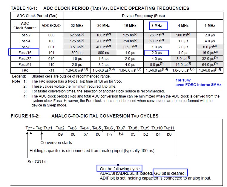
101 = 12 Tad
et en ADCS2:ADCS0 101 = FOsc/64
je pense ke les reglage sont la ou je je me plante ??
Ce que tu montres est le choix de l'horloge du CAN.Envoyé par diabolus

Tacq est une durée : temps entre ADC_ON et ADC_GO, c'est à toi de le réaliser dans le programme.
Dernière modification par antek ; 28/04/2015 à 09h28.
bonsoir,
Je ne pense pas que le probleme soit principalement sur le choix de TAD .....
2 tests realisés avec un 16F1847 ,
un à 8MHZ et choix TAD Fosc/16 ( OK dans le tableau)
un à 1Mhz et choix TAD avec FOSC/64 (Non preconisé dans le tableau)
dans les 2 cas il n'y a aucun probleme pour detecter une mesure depassant 512 point,
seuil pilotant la sortie led .
.
Test en reel et non pas en simulation .
J'ai utilisé un potar de 22K (lineaire).. pour simuler le diviseur R10K +CTN10K
Le seuil est bien situé autour de la position milieu du potar..
C'est d'ailleur un moyen bien plus fiable de tester ce bout de programme..
Le bit fin de conversion bascule bien APRES tous les TAD necessaires , si j'en crois ce tableau ?
La condition à verifier est que la division de FOSC , via la config des bits ADCS1 ADCS0 soit dans une zone valide
dans le tableau.. Apres si on choisi une frequence trop basse.. la mesure dure plus longtemps,
et peu éventuellement presenter une legere instabilité...
Il me semble qu'il doit aussi exister une delay minimum entre chaque (mesure) relance de conversion ADC.
Dans l'exemple ci dessous , A 8Mhz il y a >38µS entre chaque mesure (SANS ACTIVER la sortie sur UART ).
Code:void main() { // Internal FOSC is 500Khz by default ! OSCCON =0; // PLL disbled // 1011 => 1MHz HF OSCCON.IRCF3=1; //1 MHz OSCCON.IRCF2=0; OSCCON.IRCF1=1; OSCCON.IRCF0=1; //1110 => 8 MHz // OSCCON.IRCF3=1; // OSCCON.IRCF2=1; // OSCCON.IRCF1=1; // OSCCON.IRCF0=0; OSCCON.SCS1=1; // internal FOSC Init_Hardware() ; txt=TEXTE; // init pointeur #ifdef With_UART APFCON1.TXCKSEL=0; // TX/CK function is on RB2 UART1_Init(9600); UART1_Write(CLS); Delay_ms(500); #endif ADC_Init(); Delay_ms(100); #ifdef With_UART UART1_Write_CText("Init ADC RA3 pin2 as Analog input\r\n"); #endif j=0; ADCON0 =0; ADCON1 = 0; ADCON1.ADFM=1; // Right justified // 101 = FOSC/16 pour 8MHZ // ADCON1.ADCS2=1; // ADCON1.ADCS1=0; // ADCON1.ADCS0=1; // 110 = FOSC/54 pour 1MHZ ADCON1.ADCS2=1; ADCON1.ADCS1=1; ADCON1.ADCS0=0; ADCON1.ADNREF=0; //VREF- is connected to VSS ADCON1.ADPREF1=0; //VREF+ is connected to VDD ADCON1.ADPREF0=0; //00= VREF+ is connected to VDD ADCON0.CHS4=0; //00011 = AN3 Chanel select ADCON0.CHS3=0; ADCON0.CHS2=0; ADCON0.CHS1=1; ADCON0.CHS0=1; ADCON0.ADON=1; //Enable A/D module // no ADCON2 on 16F1847 k=0; while(1) { ADCON0.GO_NOT_DONE=1; //Start A/D Conversion while( ADCON0.GO_NOT_DONE!= 0);//Loop here until A/D conversion completes k = (ADRESH<<8) | ADRESL ; if (k >512) Led_Rouge =1; else Led_Rouge =0; #ifdef With_UART // option de compilation permettant de visualiser la valeur sur PC UART1_Write_CText("ADC= "); WordToStr(k,txt); UART1_Write_Text(txt); CRLF(); #endif }; }
je trouve ke sa je voix pas les usCode:TABLE 21-1: T AD vs. DEVICE OPERATING FREQUENCIES AD Clock Source (T AD ) Maximum Device Frequency Operation ADCS2:ADCS0 PIC18FXXXX PIC18LFXXXX (4) 2 T OSC 000 2.86 MHz 1.43 MHz 4 T OSC 100 5.71 MHz 2.86 MHz 8 T OSC 001 11.43 MHz 5.72 MHz 16 T OSC 101 22.86 MHz 11.43 MHz 32 T OSC 010 45.71 MHz 22.86 MHz 64 T OSC 110 48.0 MHz 45.71 MHz RC (3) x11 1.00 MHz (1) 1.00 MHz (2) Note 1: The RC source has a typical T AD time of 4 ms. 2: The RC source has a typical T AD time of 6 ms. 3: For device frequencies above 1 MHz, the device must be in Sleep for the entire conversion or the A/D accuracy may be out of specification. 4: Low-power devices only
bonjour,
il n'y a aucun probleme avec TAD ou FOSC ....
j'ai pu testé aussi sur un 18F2550 que j'ai sur un module MikcrorE Startup USB kit 2550
test fait avec 1MHz Fosc interne
meme Tad=12 et FOSC/64
entree ANA sur RA0
mais LEDpin sur RA1 !
Au fait, tu fais comment pour relier ta led LEDpin sur le port D avec un 18F2550 ?
dans le monde reel , bien sur..
je joins le fichier mikroC
Code:#define Version "30-04-2015 " //#define With_UART // enlever le commentaire pour avoir le resultat ADC sur la sortie UART // MikroC 6.50 // Test UART Hardware 19200bds at Q=8MHz // Project '18F2550_test_Hardw_UART.mcppi' // Source : // hardware // platine StartUSB 18F2550 de MikroE // RA0 analog input <- Potar 0 à 5V // Led RA1 // UART sur RC6 -> Tx et RC7 Rx<-- //documents //ac:StartUSB_schema //ac:Datashette_18F2550 //ac:StartUSB_docu // NE PAS OUBLIER DE MODIFIER Projet Config FOSC #define FOSC_Interne_1MHz //#define FOSC_Interne_8MHz /* avec FOSC interne 1MHZ CONFIG1L : $300000 : 0x0021 CONFIG1H : $300001 : 0x0008 CONFIG2L : $300002 : 0x0019 CONFIG2H : $300003 : 0x001E CONFIG3H : $300005 : 0x0083 CONFIG4L : $300006 : 0x0081 CONFIG5L : $300008 : 0x000F CONFIG5H : $300009 : 0x00C0 CONFIG6L : $30000A : 0x000F */ /* avec FOSC interne 8MHZ CONFIG1L : $300000 : 0x0021 CONFIG1H : $300001 : 0x0008 CONFIG2L : $300002 : 0x001F CONFIG2H : $300003 : 0x001E CONFIG3H : $300005 : 0x0083 CONFIG4L : $300006 : 0x0081 CONFIG5L : $300008 : 0x000F CONFIG5H : $300009 : 0x00C0 CONFIG6L : $30000A : 0x000F CONFIG6H : $30000B : 0x00E0 CONFIG7L : $30000C : 0x000F CONFIG7H : $30000D : 0x0040 */ sbit LEDPin at LATA1_bit; // <--OK unsigned int i,j,k; char error; char TEXTE[64]; char * txt; void UART1_Write_CText(const char *T) { while (*T) UART1_Write(*T++); } void main() { #ifdef FOSC_Interne_8MHZ // Configurer la fréquence 8MHZ pour 9600 bauds OSCTUNE =0; //=> com OK at 19200 // OSCTUNE = 0b00001000; // => very bad com at 19200 //OSCCON = 0b01111110; // System Clock Select bits OSCCON.SCS1=1; //Internal oscillator OSCCON.SCS0=0; //IRCF2:IRCF0: Internal Oscillator Frequency Select bits = 111 8Mhz OSCCON.IRCF2=1; OSCCON.IRCF1=1; OSCCON.IRCF0=1; #endif #ifdef FOSC_Interne_1MHZ OSCTUNE =0; // OSCCON = 0b01000010; OSCCON.SCS1=1; //Internal oscillator OSCCON.SCS0=0; // bit 6-4 IRCF2:IRCF0: Internal Oscillator Frequency Select bits OSCCON.IRCF2=1; // 100 => 1Mhz OSCCON.IRCF1=0; OSCCON.IRCF0=0; #endif Delay_ms(200); TRISA1_bit=0; TRISC=0xFF; LEDPin=0; // Désactiver le comparateur sur RA0 à RA3 CMCON = 0x07; // Disable comparators Delay_ms(1000); #ifdef FOSC_Interne_1Mhz UART1_Init(9600); // initialize UART1 HARDWARE module #else UART1_Init(19200); // initialize UART1 HARDWARE module #endif UART_Set_Active(&UART1_Read, &UART1_Write, &UART1_Data_Ready, &UART1_Tx_Idle); // set UART1 active TEXTE[0]=0; txt=&TEXTE[0]; UART1_Write_CText("initialisation Pointeur sur zone TEXTE\r\n"); Delay_ms(1000); #ifdef FOSC_Interne_8MHz UART1_Write_CText("StartUSB 18F2550 Init UART HARDW 19200 with FOSC Interne 8MHZ\r\n"); #endif #ifdef FOSC_Interne_1MHz UART1_Write_CText("StartUSB 18F2550 Init UART HARDW 9600 with FOSC Interne 1MHZ\r\n"); #endif ADCON0 = 0x00;// select channel 0 (AN0) ADCON1 = 0b00001110;//VSS,VDD ref. AN0 analog only ADCON1.VCFG1=0; // VREF- = VSS=0V ADCON1.VCFG0=0; // VREF+ = VDD=+5V ADCON1.PCFG3=1; ADCON1.PCFG2=1; ADCON1.PCFG1=1; ADCON1.PCFG0=0; //ADCON2 setup: Right justified, Tacq=16Tad, Tad=2*Tosc (or Fosc/2) ADCON2.ADFM=1; // right justified ADCON2.ACQT2=1; // 110 => 12 Tad ADCON2.ACQT1=0; ADCON2.ACQT0=1; ADCON2.ADCS2=1; // FOSC /64 ADCON2.ADCS2=0; ADCON2.ADCS2=1; ADCON0.ADON = 1;//Enable A/D module Delay_ms(1); while(1) { ADCON0.GO_DONE = 1;//Start A/D Conversion while(ADCON0.GO_DONE != 0);//Loop here until A/D conversion completes k = (ADRESH<<8) | ADRESL ;//Set the delay if (k >512) // > 2.5V LEDPin =1; // action si chauffe au dela de 25°C else LEDPin=0; #ifdef With_UART sprintf(txt,"k=% 5u Pts k=%04X\r\n",k,k); UART1_Write_Text(txt); Delay_ms(1000); #endif } }
bonjour merci de ton info et de ton aide pour la porteD :
sbit LEDPin at LATD1_bit; = led rd1
c la puce que j'utilise pour mes teste mais c une 4550 que je faire le circuit
je comprend tj pas d'ou vien l erreure
mon code
Code:// PIC18F4550 Configuration Bit Settings // 'C' source line config statements #include <xc.h> // #pragma config statements should precede project file includes. // Use project enums instead of #define for ON and OFF. // CONFIG1L #pragma config PLLDIV = 1 // PLL Prescaler Selection bits (No prescale (4 MHz oscillator input drives PLL directly)) #pragma config CPUDIV = OSC1_PLL2// System Clock Postscaler Selection bits ([Primary Oscillator Src: /1][96 MHz PLL Src: /2]) #pragma config USBDIV = 1 // USB Clock Selection bit (used in Full-Speed USB mode only; UCFG:FSEN = 1) (USB clock source comes directly from the primary oscillator block with no postscale) // CONFIG1H #pragma config FOSC = INTOSCIO_EC// Oscillator Selection bits (Internal oscillator, port function on RA6, EC used by USB (INTIO)) #pragma config FCMEN = OFF // Fail-Safe Clock Monitor Enable bit (Fail-Safe Clock Monitor disabled) #pragma config IESO = OFF // Internal/External Oscillator Switchover bit (Oscillator Switchover mode disabled) // CONFIG2L #pragma config PWRT = OFF // Power-up Timer Enable bit (PWRT disabled) #pragma config BOR = OFF // Brown-out Reset Enable bits (Brown-out Reset disabled in hardware and software) #pragma config BORV = 3 // Brown-out Reset Voltage bits (Minimum setting) #pragma config VREGEN = OFF // USB Voltage Regulator Enable bit (USB voltage regulator disabled) // CONFIG2H #pragma config WDT = ON // Watchdog Timer Enable bit (WDT enabled) #pragma config WDTPS = 32768 // Watchdog Timer Postscale Select bits (1:32768) // CONFIG3H #pragma config CCP2MX = ON // CCP2 MUX bit (CCP2 input/output is multiplexed with RC1) #pragma config PBADEN = ON // PORTB A/D Enable bit (PORTB<4:0> pins are configured as analog input channels on Reset) #pragma config LPT1OSC = OFF // Low-Power Timer 1 Oscillator Enable bit (Timer1 configured for higher power operation) #pragma config MCLRE = OFF // MCLR Pin Enable bit (RE3 input pin enabled; MCLR pin disabled) // CONFIG4L #pragma config STVREN = ON // Stack Full/Underflow Reset Enable bit (Stack full/underflow will cause Reset) #pragma config LVP = ON // Single-Supply ICSP Enable bit (Single-Supply ICSP enabled) #pragma config ICPRT = OFF // Dedicated In-Circuit Debug/Programming Port (ICPORT) Enable bit (ICPORT disabled) #pragma config XINST = OFF // Extended Instruction Set Enable bit (Instruction set extension and Indexed Addressing mode disabled (Legacy mode)) // CONFIG5L #pragma config CP0 = OFF // Code Protection bit (Block 0 (000800-001FFFh) is not code-protected) #pragma config CP1 = OFF // Code Protection bit (Block 1 (002000-003FFFh) is not code-protected) #pragma config CP2 = OFF // Code Protection bit (Block 2 (004000-005FFFh) is not code-protected) #pragma config CP3 = OFF // Code Protection bit (Block 3 (006000-007FFFh) is not code-protected) // CONFIG5H #pragma config CPB = OFF // Boot Block Code Protection bit (Boot block (000000-0007FFh) is not code-protected) #pragma config CPD = OFF // Data EEPROM Code Protection bit (Data EEPROM is not code-protected) // CONFIG6L #pragma config WRT0 = OFF // Write Protection bit (Block 0 (000800-001FFFh) is not write-protected) #pragma config WRT1 = OFF // Write Protection bit (Block 1 (002000-003FFFh) is not write-protected) #pragma config WRT2 = OFF // Write Protection bit (Block 2 (004000-005FFFh) is not write-protected) #pragma config WRT3 = OFF // Write Protection bit (Block 3 (006000-007FFFh) is not write-protected) // CONFIG6H #pragma config WRTC = OFF // Configuration Register Write Protection bit (Configuration registers (300000-3000FFh) are not write-protected) #pragma config WRTB = OFF // Boot Block Write Protection bit (Boot block (000000-0007FFh) is not write-protected) #pragma config WRTD = OFF // Data EEPROM Write Protection bit (Data EEPROM is not write-protected) // CONFIG7L #pragma config EBTR0 = OFF // Table Read Protection bit (Block 0 (000800-001FFFh) is not protected from table reads executed in other blocks) #pragma config EBTR1 = OFF // Table Read Protection bit (Block 1 (002000-003FFFh) is not protected from table reads executed in other blocks) #pragma config EBTR2 = OFF // Table Read Protection bit (Block 2 (004000-005FFFh) is not protected from table reads executed in other blocks) #pragma config EBTR3 = OFF // Table Read Protection bit (Block 3 (006000-007FFFh) is not protected from table reads executed in other blocks) // CONFIG7H #pragma config EBTRB = OFF // Boot Block Table Read Protection bit (Boot block (000000-0007FFh) is not protected from table reads executed in other blocks) #define LEDpin LATDbits.LATD4 #define LEDTris TRISDbits.TRISD4 void main() { int delay; LEDpin=1; LEDTris=0; ADCON1 = 0b00001110;//VSS,VDD ref. AN0 analog only ADCON0 = 0x00;//clear ADCON0 to select channel 0 (AN0) ADCON2 = 0b10001000;//ADCON2 setup: Right justified, Tacq=2Tad, Tad=2*Tosc (or Fosc/2) ADCON0bits.ADON = 0x01;//Enable A/D module while(1) { ADCON0bits.GO_DONE = 1;//Start A/D Conversion while(ADCON0bits.GO_DONE != 0);//Loop here until A/D conversion completes delay = ADRESH<<8 + ADRESL ;//Set the delay if (delay > 612) // > 25°C LEDpin =1; // action si chauffe au dela de 25°C else LEDpin =0; } }
Dernière modification par Antoane ; 06/09/2015 à 17h45. Motif: Ajout balises [code]
Code:// Désactiver le comparateur sur RA0 à RA3 CMCON = 0x07; // Disable comparators
jais un probleme avec le programe ou autre la led reste pas allumuler au dessu de la valeur ni en dessou mais pile poile a la valeur ce nest pas normale je petiene sur ce bug
jais un potar de 10k +et anal et 10 entre - et anal
aurais pas oublier kel que chose.. un delay ..ou autre
jais trouver merci #delay = ADRESH<<8 + ADRESL ;//Set the delay #
mais pluto sa #k = (ADRESH<<8) | ADRESL ;#
je le faire fonctionner correctement je sait pas ou et mon defaut helps me plisCode:#include <p18f4550.h> #include<htc.h> #include<stdlib.h> #include<stdio.h> #include <xc.h> // #pragma config statements should precede project file includes. // Use project enums instead of #define for ON and OFF. // CONFIG1L #pragma config PLLDIV = 1 // PLL Prescaler Selection bits (No prescale (4 MHz oscillator input drives PLL directly)) #pragma config CPUDIV = OSC1_PLL2// System Clock Postscaler Selection bits ([Primary Oscillator Src: /1][96 MHz PLL Src: /2]) #pragma config USBDIV = 1 // USB Clock Selection bit (used in Full-Speed USB mode only; UCFG:FSEN = 1) (USB clock source comes directly from the primary oscillator block with no postscale) // CONFIG1H #pragma config FOSC = INTOSCIO_EC// Oscillator Selection bits (Internal oscillator, port function on RA6, EC used by USB (INTIO)) #pragma config FCMEN = OFF // Fail-Safe Clock Monitor Enable bit (Fail-Safe Clock Monitor disabled) #pragma config IESO = OFF // Internal/External Oscillator Switchover bit (Oscillator Switchover mode disabled) // CONFIG2L #pragma config PWRT = OFF // Power-up Timer Enable bit (PWRT disabled) #pragma config BOR = OFF // Brown-out Reset Enable bits (Brown-out Reset disabled in hardware and software) #pragma config BORV = 1 // Brown-out Reset Voltage bits (Minimum setting) #pragma config VREGEN = OFF // USB Voltage Regulator Enable bit (USB voltage regulator disabled) // CONFIG2H #pragma config WDT = OFF // Watchdog Timer Enable bit (WDT enabled) #pragma config WDTPS = 32768 // Watchdog Timer Postscale Select bits (1:32768) // CONFIG3H #pragma config CCP2MX = ON // CCP2 MUX bit (CCP2 input/output is multiplexed with RC1) #pragma config PBADEN = ON // PORTB A/D Enable bit (PORTB<4:0> pins are configured as analog input channels on Reset) #pragma config LPT1OSC = OFF // Low-Power Timer 1 Oscillator Enable bit (Timer1 configured for higher power operation) #pragma config MCLRE = OFF // MCLR Pin Enable bit (RE3 input pin enabled; MCLR pin disabled) // CONFIG4L #pragma config STVREN = OFF // Stack Full/Underflow Reset Enable bit (Stack full/underflow will cause Reset) #pragma config LVP = OFF // Single-Supply ICSP Enable bit (Single-Supply ICSP enabled) #pragma config ICPRT = ON // Dedicated In-Circuit Debug/Programming Port (ICPORT) Enable bit (ICPORT disabled) #pragma config XINST = OFF // Extended Instruction Set Enable bit (Instruction set extension and Indexed Addressing mode disabled (Legacy mode)) // CONFIG5L #pragma config CP0 = OFF // Code Protection bit (Block 0 (000800-001FFFh) is not code-protected) #pragma config CP1 = OFF // Code Protection bit (Block 1 (002000-003FFFh) is not code-protected) #pragma config CP2 = OFF // Code Protection bit (Block 2 (004000-005FFFh) is not code-protected) #pragma config CP3 = OFF // Code Protection bit (Block 3 (006000-007FFFh) is not code-protected) // CONFIG5H #pragma config CPB = OFF // Boot Block Code Protection bit (Boot block (000000-0007FFh) is not code-protected) #pragma config CPD = OFF // Data EEPROM Code Protection bit (Data EEPROM is not code-protected) // CONFIG6L #pragma config WRT0 = OFF // Write Protection bit (Block 0 (000800-001FFFh) is not write-protected) #pragma config WRT1 = OFF // Write Protection bit (Block 1 (002000-003FFFh) is not write-protected) #pragma config WRT2 = OFF // Write Protection bit (Block 2 (004000-005FFFh) is not write-protected) #pragma config WRT3 = OFF // Write Protection bit (Block 3 (006000-007FFFh) is not write-protected) // CONFIG6H #pragma config WRTC = OFF // Configuration Register Write Protection bit (Configuration registers (300000-3000FFh) are not write-protected) #pragma config WRTB = OFF // Boot Block Write Protection bit (Boot block (000000-0007FFh) is not write-protected) #pragma config WRTD = OFF // Data EEPROM Write Protection bit (Data EEPROM is not write-protected) // CONFIG7L #pragma config EBTR0 = OFF // Table Read Protection bit (Block 0 (000800-001FFFh) is not protected from table reads executed in other blocks) #pragma config EBTR1 = OFF // Table Read Protection bit (Block 1 (002000-003FFFh) is not protected from table reads executed in other blocks) #pragma config EBTR2 = OFF // Table Read Protection bit (Block 2 (004000-005FFFh) is not protected from table reads executed in other blocks) #pragma config EBTR3 = OFF // Table Read Protection bit (Block 3 (006000-007FFFh) is not protected from table reads executed in other blocks) // CONFIG7H #pragma config EBTRB = OFF // Boot Block Table Read Protection bit (Boot block (000000-0007FFh) is not protected from table reads executed in other blocks) //#define CMCON = 0x07; // Disable comparators #define _XTAL_FREQ 4000000 //#define RD3 LATDbits.LATD3 #define RD3 TRISDbits.TRISD3 //#define RD2 LATDbits.LATD3 #define RD2 TRISDbits.TRISD2 //#define RD1 LATDbits.LATD1 #define RD1 TRISDbits.TRISD1 //#define RD0 LATDbits.LATD0 #define RD0 TRISDbits.TRISD0 void delay(unsigned int N){ unsigned int i; for(int i=0; i < N; i++) Nop(); } unsigned short i, D0,D1,D2,D3; unsigned int Count; unsigned short mask(unsigned short num){ switch (num) { case 0 : return 0xC0; case 1 : return 0xF9; case 2 : return 0xA4; case 3 : return 0xB0; case 4 : return 0x99; case 5 : return 0x92; case 6 : return 0x82; case 7 : return 0xF8; case 8 : return 0x80; case 9 : return 0x90; } //case end } void main(void) { Count = 0; // Initial Value of Counter while(1) { //Count = 0; // Initial Value of Counter D0 = Count%10; // Extract Ones Digit D0 = mask(D0); D1 = (Count/10)%10; // Extract Tens Digit D1 = mask(D1); D2 = (Count/100)%10; // Extract Hundreds Digit D2 = mask(D2); D3 = (Count/1000)%10; // Extract Thousands Digit D3 = mask(D3); TRISA=0x00; TRISD=0xff; TRISB=0x00; //int k = 0 ; //while(k<=10) //{ PORTB = D0; RD0 = 0; // Select Ones Digit RD1 = 1; RD2 = 1; RD3 = 1; delay(500); PORTB = D1; RD0 = 1; RD1 = 0; // Select Tens Digit RD2 = 1; RD3 = 1; delay(500); PORTB= D2; RD0 = 1; RD1 = 1; RD2 = 0; // Select Hundreds Digit RD3 = 1; delay(500); PORTB= D3; RD0 = 1; RD1 = 1; RD2 = 1; RD3 = 0; // Select Thousands Digit delay(500); // k++; //} Count = Count + 1 ; delay(100); if (Count > 999) Count = 0; } }
Dernière modification par Antoane ; 11/09/2015 à 16h41. Motif: Remplacement des balises quote par code
le deconte de 1er affficheur marche mais des que je met les autre sa beug