


Bonjour,
J'essaye de de générer un signal pwm en utilisant les comparateurs internes au micro, comme il est expliqué dans la section :"16.9 Hysteresis Current Control Mode" page 109 du Reference Manual DS70000323G ( http://ww1.microchip.com/downloads/e.../70000323g.pdf ) ce pendant quand j'implémente le code donné dans cette section le résultat obtenue ne correspond pas du tout aux explications en effet, le signal PWM1H bascule à l'état Haut (3.3V) quand on applique une tension de 3.3V sur la pin 2 (CMP1A) et repasse à l'état bas (0V) dès que l'on n'y applique plus les 3.3V. De plus on observe aucun changement d'état de la PWM quand on applique une tension de 0.8V sur la pin 4 (/CMP2A). Or le signal PWM devrait passer à '1' quand on atteint la limite basse soit le faite d'appliquer une tension inférieure à 1.2V sur la pin 4 et rester à '1' tant qu'une tension supérieur à 2.9V n'est pas appliqué sur la pin 2.
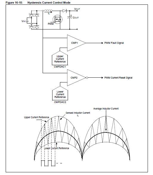
comme le montre le schéma ci-dessus:
Et comme le confirme le texte ci-dessous:
In low-power applications, such as Power Factor Correction, the Continuous Conduction mode
of operation is achieved through control of the inductor current within an upper current-limit and
a lower current-limit. This application results in a Variable Frequency mode of operation and this
control scheme is called the Hysteresis Current Control mode. Hysteresis Current Control mode
can be achieved using two high-speed analog comparators. In order to implement the Hysteresis
Current Control mode, the PWM module uses both the Cycle-by-Cycle Fault Limit mode and
Current Reset mode.
For example, consider a Boost Converter, whose inductor current is to be controlled using
Hysteresis Current Control mode, as shown in Figure 16-10.
When the MOSFET is turned on, the inductor current increases. When the current reaches the
upper limit (configured in the DAC of the first comparator), the PWM output is made low and the
MOSFET is turned off (PWM Fault source is configured as the output of the first comparator),
then the current through the inductor starts decreasing. Once the current reaches the lower limit,
it is detected using the second comparator (configured in Inverted Polarity mode) and the output
of the second comparator is used as the signal for resetting the PWM period. Example 16-2
shows a code snippet for initialization of the PWM and comparator modules for devices with
remappable I/Os.
Voici le code complet que j'ai utilisé pour mes essai:
Si quelqu'un a une explication, solution à mon problème je suis preneur car là je ne vois pas ce qui cloche.Code:/******************************************************************************/ /* Bits configuration */ /******************************************************************************/ _FOSCSEL(FNOSC_PRI & IESO_ON); //Select Internal FRC at POR _FOSC(FCKSM_CSECMD & OSCIOFNC_ON); //Only clock Switching enabled //(Fail Safe Clock Monitor is disabled) _FWDT(WDTEN_OFF); _FICD(ICS_PGD2 & JTAGEN_OFF); _FDEVOPT(PWMLOCK_OFF); /******************************************************************************/ /* Main */ /******************************************************************************/ int main(void){ /*-------------------------------Initialisation-------------------------------*/ initOscillator(); initPWM(); initComparator (); /*-------------------------------Infinity Loop--------------------------------*/ while(1){ } return 0; } /******************************************************************************/ /* Function */ /******************************************************************************/ /*-----------------------------Configure Oscillator---------------------------*/ void initOscillator (void){ RCONbits.SWDTEN=0; //Disable Watch Dog Timer //Configure Oscillator to operate the device at 68 MHz //Fosc = Fin*M/(N1*N2), Fcy = Fosc/2 //Fosc = 7.37*(76)/(2*2)= ~140Mhz for Fosc, Fcy = 70 MHz //Configure PLL prescaler, PLL postscaler, PLL divisor PLLFBD = 74; //M = PLLFBD + 2 CLKDIVbits.PLLPOST = 0; //N1 = 2 CLKDIVbits.PLLPRE = 0; //N2 = 2 __builtin_write_OSCCONH(0x01); //New Oscillator selection FRC w/ PLL __builtin_write_OSCCONL(0x01); //Enable Switch while(OSCCONbits.COSC != 0b001); //Wait for Osc. to switch to FRC w/ PLL while(OSCCONbits.LOCK != 1); //Wait for PLL to Lock //Setup the ADC and PWM clock for 120MHz //((FRC * 16) / APSTSCLR ) = (7.37MHz * 16) / 1 = 117.9MHz ACLKCONbits.FRCSEL = 1; //FRC provides input for Auxiliary PLL (x16) ACLKCONbits.SELACLK = 1; //Aux Osc. provides clock source for PWM & ADC ACLKCONbits.APSTSCLR = 7; //Divide Auxiliary clock by 1 ACLKCONbits.ENAPLL = 1; //Enable Auxiliary PLL while(ACLKCONbits.APLLCK != 1); //Wait for Auxiliary PLL to Lock RCONbits.SWDTEN=1; //Enable Watch Dog Timer } void initPWM (void){ /* Initializing PWM1 Generator for controlling MOSFET */ PWMCON1bits.ITB = 1; /* Select independent time base for enabling XPRES */ PWMCON1bits.XPRES = 1; /* Select Current Reset mode */ IOCON1bits.PMOD = 1; /* Select Redundant mode since only PWM1H is being used for MOSFET */ IOCON1bits.FLTDAT = 0; /* To make the PWM signals low during Fault condition */ FCLCON1bits.FLTSRC = 0b01101; /* Select Analog Comparator1 as Fault Source for PWM1 */ FCLCON1bits.FLTMOD = 1; /* Select Cycle-by-cycle Fault mode for upper limit cut-off */ FCLCON1bits.CLSRC = 0b01110; /* Select Analog Comparator2 as Current Limit Source for Current Reset of PWM1 */ } void initComparator (void){ /* Configuring ACMP1 for Upper Current Limit and ACMP2 for Lower Current Limit */ CMP1CONbits.RANGE = 1; /* Set Maximum DAC output voltage to AVDD */ CMP1DAC = 3600; /* Configure to turn OFF MOSFET at 2.9V of comparator input (upper current reference) */ CMP1CONbits.CMPON = 1; /* Turn ON Analog Comparator1 */ CMP2CONbits.RANGE = 1; /* Set Maximum DAC output voltage to AVDD */ CMP2CONbits.CMPPOL = 1; /* Invert output polarity of Analog Comparator 2 for lower limit current detection and PWM Reset */ CMP2DAC = 1489; /* Configure to reset PWM at 1.2V of comparator input (lower current reference */ CMP2CONbits.CMPON = 1; /* Turn ON Analog Comparator2 */ }
Merci par avance.
-----